Tesla Battery Pack Architecture – Understanding the Design
Tesla’s battery packs are built using thousands of Panasonic 18650 lithium-ion cells arranged in a series-parallel configuration. While there are many variations across different models and years, the fundamental structure remains similar.
Key Features of Tesla Battery Packs:
- Most Model S/X packs contain 14 or 16 modules, depending on the version.
- Some packs are software-locked by Tesla, meaning they have the same physical cell and module configuration as higher-capacity packs but are limited in usable energy.
- Older basic packs contain 74 cells per brick, while newer ones have 86 cells per brick, increasing energy density without changing form factor.
- Packs vary in capacity from 40kWh (smallest) to 100kWh (largest).
- There are 90kWh packs with both 350V and 400V configurations, adding further complexity.
Example: The 85kWh Pack (2012-2015)
For reference, the 85kWh pack was a major high-capacity option in early Tesla models. It serves as a good baseline for understanding Tesla’s battery architecture before the introduction of newer variants.
⚡ With so many variations in voltage, module count, and software limitations, always verify the specifics of your pack before making modifications!
Tesla Battery Pack – Key Definitions & Structure
Understanding Tesla’s battery pack design requires breaking it down into its core components: Cells, Bricks, Modules, and the full Pack. Here’s how it all fits together:
Series and Parallel Basics
- Parallel connections: All + terminals connect together, and all – terminals connect together. This keeps voltage the same but increases capacity (e.g., jump-starting a car).
- Series connections: Each + terminal connects to the – terminal of the next cell, increasing voltage (e.g., two 1.5V AA batteries powering a 3V flashlight).
- Tesla’s battery packs combine both methods to balance voltage and capacity.
Cell
- The smallest unit, an 18650 lithium-ion cell, is 18mm in diameter and 65mm tall.
- A fully charged cell is slightly above 4V, while an empty one is just below 3V (values vary by chemistry).
- It resembles an oversized AA battery and is commonly used in rechargeable electronics.
Brick
- A brick is a set of 74 cells (for an 85kWh pack) or 86 cells (for newer packs) connected in parallel.
- The voltage remains at ~4V, but since all cells share connections, the energy storage is multiplied by 74 or 86.
- ⚠ ScanMyTesla Mislabeling: The app refers to Bricks as ‘Cells’ in its readings, but it does not measure individual 18650 cells—only Bricks.
Module
- A module consists of six Bricks in series, increasing the total voltage to ~24V (6 x 4V).
- Bricks are arranged in an alternating up-down pattern for efficiency.
- A module contains 444 cells (for 85kWh packs) or 516 cells (for newer packs).
- This configuration ensures that all Bricks contribute equally to energy distribution.
Full Battery Pack (HV Pack)
- A full pack consists of 16 modules in series (each module’s + connects to the next module’s –).
- This results in a total voltage of ~400V (16 x 24V).
- The physical layout:
- Module #1 is at the back-left, and Module #7 is at the front-left.
- Modules #8 & #9 are stacked in the ‘hump’ at the front, with #9 mounted upside down (the only one in the pack).
- Module #10 is across from #7, and Module #16 is at the back-right across from #1.
- In 14-module (90kWh) packs, the ‘hump’ is empty, keeping consecutive numbering.
Understanding this layout is crucial for repairs, modifications, or diagnostics of Tesla’s high-voltage system. 🚗⚡
The High Voltage Bus
Tesla’s High Voltage (HV) bus routes power through the 16 battery modules in series, but the actual wiring layout isn’t as straightforward as you might expect.
How You Might Expect It to Work (But It Doesn’t)
A simple series connection would mean:
- Module #1 connects directly to a contactor on one end.
- Module #16 connects to the other contactor at the opposite end.
- The modules would link in a simple up/down sequence, with a fuse in the middle.
However, this intuitive design would result in 400V potential across the spine of the battery pack—right where the metal lid is removed during service. That would pose a major safety hazard! ⚠️
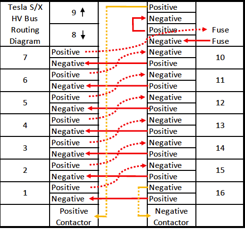
How Tesla Actually Routes the HV Bus (Safer Zig-Zag Design)
- Tesla runs a bus bar along the length of the pack and uses a zig-zag pattern across the center spine.
- Why? This keeps the voltage difference between adjacent connection points low—a maximum of 48V instead of 400V.
- The + and – terminals are placed close together and insulated with just a rubber cap instead of needing heavy-duty isolation.
- This design significantly reduces the risk of accidental high-voltage exposure when opening or working inside the pack.
Why This Matters for Repairs & Modifications
- If you ever need to open the pack, this layout makes it far safer than it would have been with a direct-series configuration.
- It’s crucial to understand the zig-zag path when troubleshooting the pack or testing connections.
Tesla’s thoughtful HV bus routing prioritizes safety while maintaining efficiency—a key reason why their battery packs are among the safest on the road. ⚡🔋
Isolation Fault
What Does It Mean and Why Is It Dangerous?
An isolation fault in a Tesla battery pack is a serious electrical issue that makes working around high voltage (HV) much more dangerous. Understanding what it means is crucial for safety when handling the pack.
What is an Isolation Fault?
Normally, a battery pack’s energy is completely isolated inside the pack—it should not be connected to the metal case or chassis. To visualize this, think of a 9V battery:
- If you place a voltmeter probe on the + terminal and the other on the – terminal, you get a voltage reading. ✅
- If you place one probe on either terminal and the other on the metal case of the battery, you get nothing because the energy is fully contained inside the battery. ✅
This is how all batteries, including Tesla’s HV pack, should behave under normal conditions.
What Happens in an Isolation Fault?
Now imagine that you do get a voltage reading between the + terminal and the case of the 9V battery. That means the energy inside is leaking into the metal casing. ❌ This is a big problem.
For a 9V battery, it wouldn’t matter much—it’s low voltage and won’t hurt you. But for a Tesla pack, an isolation fault means high-voltage electricity is making unintended contact with the pack’s casing or other components.
Tesla’s built-in isolation detection circuit continuously checks for leaks. If a problem is detected, it means:
⚠️ The pack may no longer be fully isolated, making it dangerous to work on.
Why Is This a Serious Safety Hazard?
- If the HV bus is leaking energy to the metal case, touching both could complete the circuit—and zap you.
- Tesla’s isolation circuit allows a small test voltage to check for faults, meaning you could still get a painful shock if you touch the wrong point. (Think taser-level pain—not always fatal, but extremely dangerous).
- Every safety procedure should be followed even more slowly and carefully if an isolation fault is present.
What You Should Do If There’s an Isolation Fault
- Do NOT assume the pack is safe at any point.
- Treat every metal surface as potentially energized.
- Use proper PPE (high-voltage gloves, insulated tools).
- Follow Tesla’s safety protocols carefully—slow, methodical work is key.
- Never test HV connections with a standard multimeter—use only proper HV-rated tools.
- Watch Weber Auto’s YouTube video on loss of isolation for a deeper understanding.
⚠ Final Warning:
An isolation fault means the pack is no longer behaving like a normal battery—it could shock you unexpectedly. Work slowly and methodically until the fault is fully diagnosed and resolved. High-voltage mistakes are unforgiving! ⚡🔥
High Voltage Interlock Loop (HVIL) – Tesla’s Safety Circuit
The HVIL (High Voltage Interlock Loop) is a critical safety system in Tesla vehicles that ensures all high-voltage (HV) components remain safely connected. If the HVIL detects an issue, it opens the loop, which shuts down the high-voltage system by disconnecting the contactors inside the battery pack—effectively disabling HV power.
How HVIL Works
- The HVIL links all HV components in a series circuit (battery, inverter, chargers, DC-DC converter, etc.).
- If any component detects a fault, the HVIL opens, and the battery pack’s contactors disconnect to prevent unsafe conditions.
- When this happens, you’ll see errors on the MCU and in service mode, attempting to pinpoint the faulty component.
- Some error messages provide specific details, while others may be more general, requiring further diagnostics.
Manually Disabling HVIL (Fireman’s Loop)
- Location: At the base of the windshield on the right-hand side of the vehicle.
- Purpose: This first responder safety feature is designed to be cut in emergencies to disable the HV system.
- For service work: Instead of cutting it, unplugging the Fireman’s Loop opens the HVIL manually, allowing safe work on HV components.
HVIL vs. Isolation Fault – Key Difference
⚠ HVIL and Isolation Faults are NOT the same issue!
- An HVIL error means the safety circuit detected a disconnected or faulty HV component, causing the system to shut down.
- An Isolation Fault means high voltage is leaking somewhere it shouldn’t be—posing a direct electrical shock risk.
- Diagnosis and repair processes are different, so make sure you correctly identify which issue is occurring.
Final Notes
- Always unplug the Fireman’s Loop before performing HV work.
- If an HVIL error appears unexpectedly, check connectors, fuses, and component status before assuming a failure.
- Be cautious—while HVIL protects against some dangers, it does not eliminate all HV risks. Always use proper PPE and tools when handling high-voltage components.